Address
304 North Cardinal
St. Dorchester Center, MA 02124
Work Hours
Monday to Friday: 7AM - 7PM
Weekend: 10AM - 5PM
Address
304 North Cardinal
St. Dorchester Center, MA 02124
Work Hours
Monday to Friday: 7AM - 7PM
Weekend: 10AM - 5PM
The second repair of ASUS Flying Fortress FX86F notebook does not trigger.
Machine model: Asus Flying Fortress FX86F
Fault symptom: the notebook does not trigger.
Maintenance process:
An ASUS flying fortress FX86F second repair machine, the fault is that the notebook does not trigger, and the 3.3V 5V power chip has been replaced.
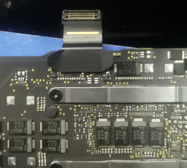
After disassembling the machine, it is found that the standby voltage of 3.3V, 5V and South Bridge 1.0V is normal. According to the maintenance experience of ASUS, the standby voltage of ASUS is usually turned off after reading the EC configuration information in BIOS instantly, waiting for the button to trigger, but the test of this machine finds that the standby voltage is always on.
The second repair of ASUS Flying Fortress FX86F notebook does not trigger Figure 1.
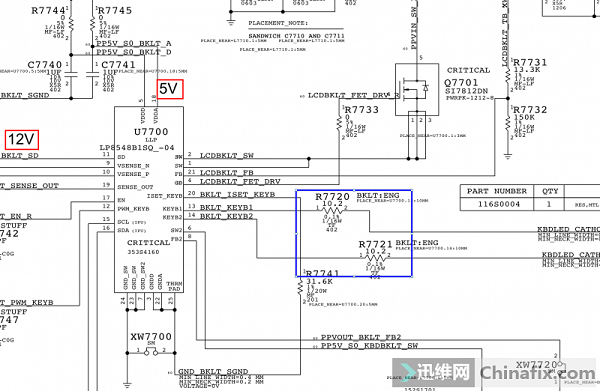
According to the drawing, look for the 3.3V 5V turn-on signal from VSUS_ON.
The second repair of ASUS Flying Fortress FX86F notebook does not trigger Figure 2.
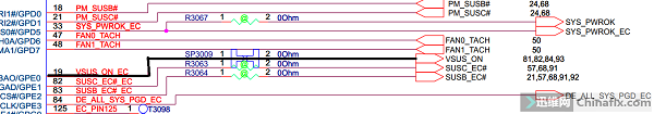
Searching for VSUS_ON found that the signal was sent by the EC 19 pin and passed through SP3009. The SP3009 was disconnected to measure the EC 19 pin, and it was always in a high level state when it was powered on. Direct exchange EC(IT8987E) still fails. If the working conditions of EC are abnormal, the SPI bus from BIOS to EC is normal, and it cannot be triggered by pressing the power-on key. Changing the south bridge is also invalid.
According to the signal search, PM_RSMRST and PM_PWRBTN are measured, and both signals are found to be abnormal. Test the memory power supply, and find that the memory power supply comes out for a few tenths of a second at the moment of power-on. Continue to measure that VCCIO and VCCSA power off at the moment of power-on, but there is no CPU power supply.
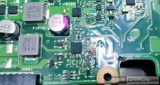
Measure the power supply condition of CPU, and check that the CPU power chip SCLK SDA has no signal and no voltage.
The second repair of ASUS Flying Fortress FX86F notebook does not trigger Figure 3
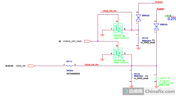
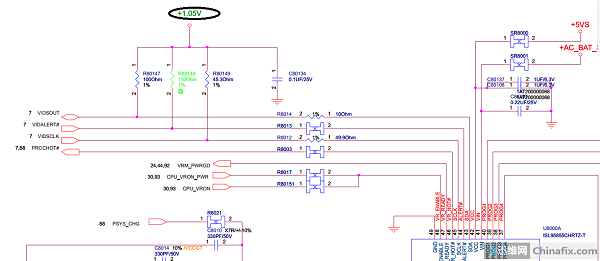
The pull-up voltage of 1.05V on the measuring bus is 0, and the resistance is about 150.
The second repair of ASUS Flying Fortress FX86F notebook does not trigger Figure 4.
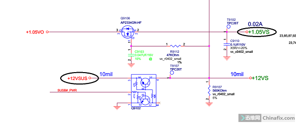
Looking up, it is known that 1.05V comes from Q9106, and the voltage at the pin of Q9106 is 1.05V, and the voltage at the pin of Q9106 is 0 V. Q9106 is not conductive. Measure the voltage source of the first pin of Q9106, and the voltage source of the third pin of Q9102 is also 0V.
The second repair of ASUS Flying Fortress FX86F notebook does not trigger Figure 5.
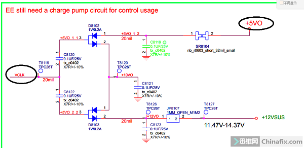
Looking up the pump voltage boost of 12VSUS from standby power supply, it is found that there is 5V by direct measurement of JP8107. Theoretically, even if there is a load of 15V, the voltage drop should actually be above 10V. It is found that the voltage of +5VO is 5V, and the pump power supply drives VCLK 0V, but the pump power supply does not.
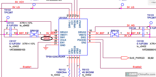
The second repair of ASUS Flying Fortress FX86F notebook does not trigger Figure 6
After consulting the drawings, it is concluded that the pump power supply VCLK comes from the standby chip pin 19, and it is worried that the short circuit of components will lower VCLK. When the circuit is disconnected, there is still no VCLK output at the pin 19, and the replaced chip still cannot produce VCLK. Find chip information introduction.
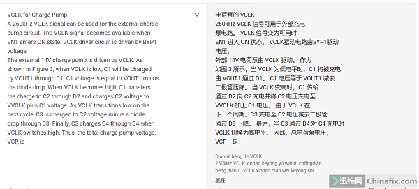
The second repair of ASUS Flying Fortress FX86F notebook does not trigger Figure 7
The introduction of VCLK in RT6575B probably means that VCLK is a pulse signal of 260Khz. When EN1 is high, it is driven by YP1, and EN1 that works at 3.3V and 5V must be high, so the high probability problem lies in YP1.
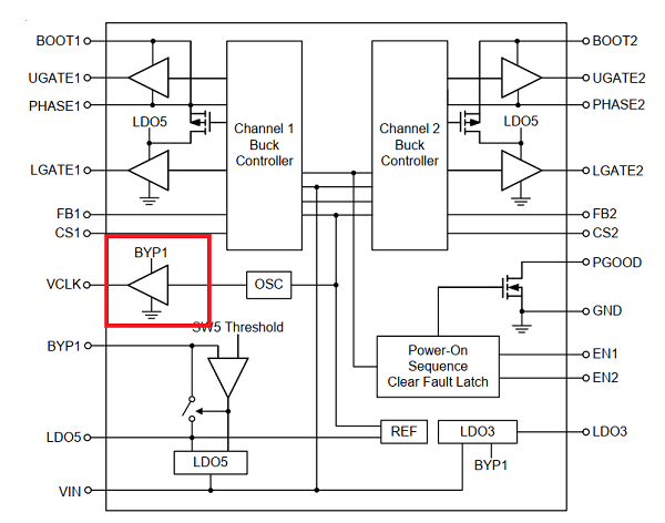
The second repair of ASUS Flying Fortress FX86F notebook does not trigger Figure 8.
Looking at the chip block diagram, we know that the power supply of VCLK pump power-driven oscillator is directly connected to BYP1.
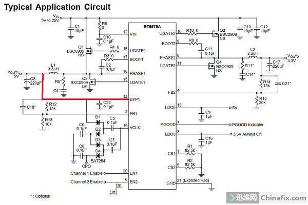
The second repair of ASUS Flying Fortress FX86F notebook does not trigger Figure 9.
Looking at the typical diagram of the chip, it can be seen that BYP1 is directly connected with 5V output, and the pin of BYP1 of this chip should have 5V voltage.
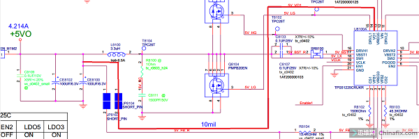
The second repair of ASUS Flying Fortress FX86F notebook does not trigger Figure 10.
BYP1 is the 14 pins of the chip, and the 14 pins are VO1, which are also connected to 5V through JP8104. The pin VO1 of that measure chip 14 is 0V, and there is no voltage. Measure that the voltage of JP8104 is 5V, which is normal. It is that there is a disconnection from JP8104 to the chip. Check the circuit and find that it has entered the bottom of the CMOS battery holder. When the CMOS battery holder is removed, it is found that there is liquid corrosion.
Scraping corrosion found that two wires were broken, namely VO1 5V on the left side and 12VSUS on the right side of standby chip 14, and the green oil for repairing wires was solidified. Installation test, perfect lighting, all functions are normal, troubleshooting and maintenance are over.
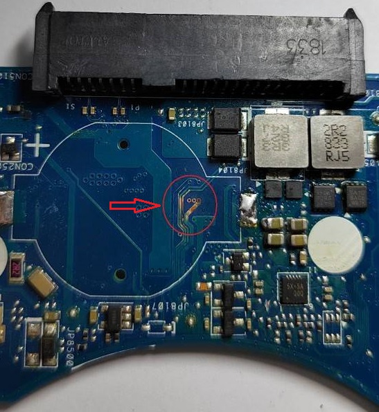
The second repair of ASUS Flying Fortress FX86F notebook does not trigger Figure 11.