Address
304 North Cardinal
St. Dorchester Center, MA 02124
Work Hours
Monday to Friday: 7AM - 7PM
Weekend: 10AM - 5PM
Address
304 North Cardinal
St. Dorchester Center, MA 02124
Work Hours
Monday to Friday: 7AM - 7PM
Weekend: 10AM - 5PM
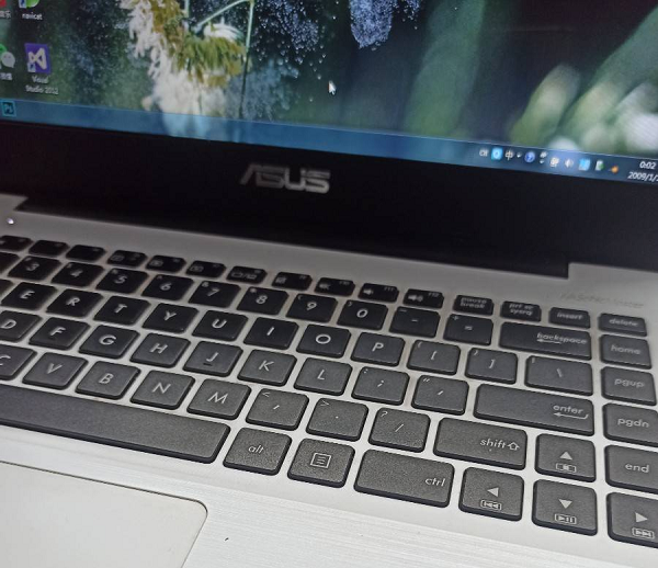
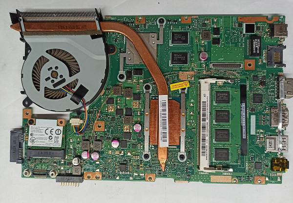
ASUS X455LD notebook computer usb interface all failed repair
First plug in the USB mouse for testing, and the visual mouse light is not on, which is due to the lack of USB+5V power supply. After the flying line, USB_P1 on the small board is connected to USB_P6;; USB_P2 to USB_P4. The test can identify the use of USB devices. Just give up the function of the camera, but don’t have to change the CPU at a high price.
[machine model] ASUS X455LD
[Failure phenomenon] All usb interfaces of notebook computers are invalid.
[maintenance process]
I received an ASUS X455LD notebook computer, and the fault description shows that all usb interfaces have failed. First plug in the USB mouse to test, and the mouse light is not lit visually, which is due to the lack of USB+5V power supply.
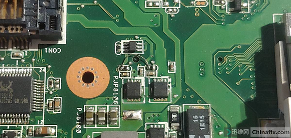
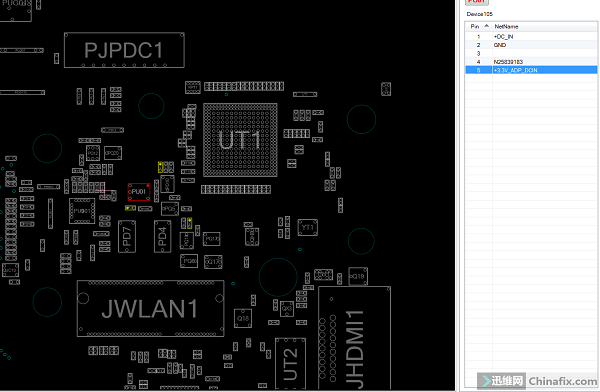
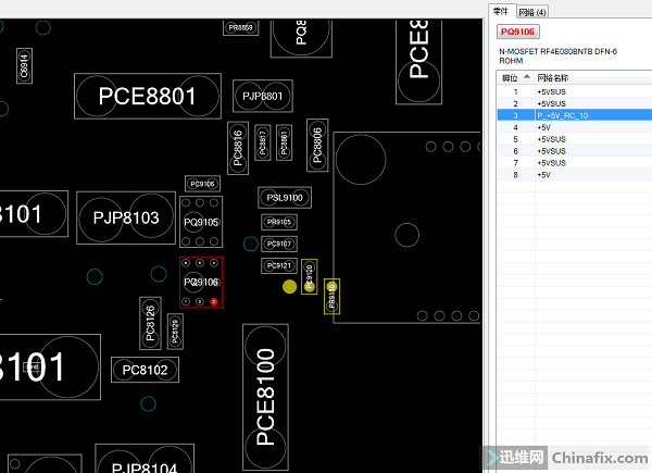
Remove the motherboard and check that the USB power supply terminal has no electricity and no short circuit to the ground. According to the time sequence, it is supplied by the fourth output of PQ9106. The measured voltages of PQ9106 1, 2, 5 and 6P are 5V normal, 4P = 0V, and 3P’s control electrode = 0V abnormal. This control signal named P_+5V_RC_10 is renamed +12V after passing through PR9110/100K resistor. As the name implies, the normal voltage of +12V is 1V.
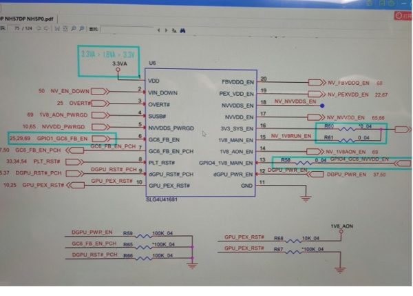
+12V is provided by the 3P output of PQ9111, which is a 6-pin composite pipe. The PDF is as follows:
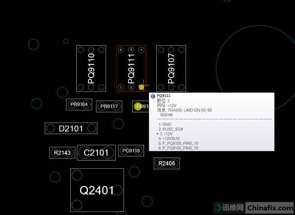
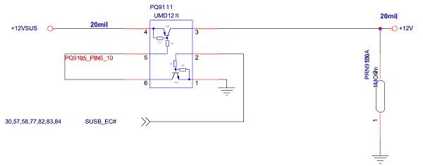
It can be seen from the figure that PQ9111 is a triode composed of PNP and NPN. Measured 2P=3.3V is normal, 5P, 6P=0V is normal, 4P=12V is normal, and 3P=0V is abnormal, which means that the PNP triode in the composite pipe is broken and does not conduct. The composite pipe model is UMD12N, and a PNP triode is connected externally. Find a PNP transistor.
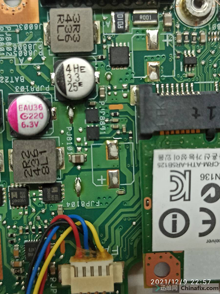
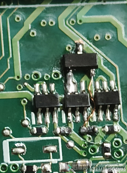
Start to lap, and +12V comes out.
With the 12V control signal, the USB power supply is also restored. Only the USB3.0 interface can be used in the test. The two USB ports leading to the small board still can’t be used, but there is power supply.
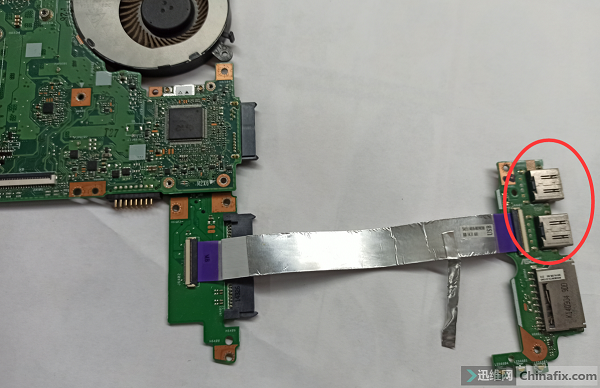
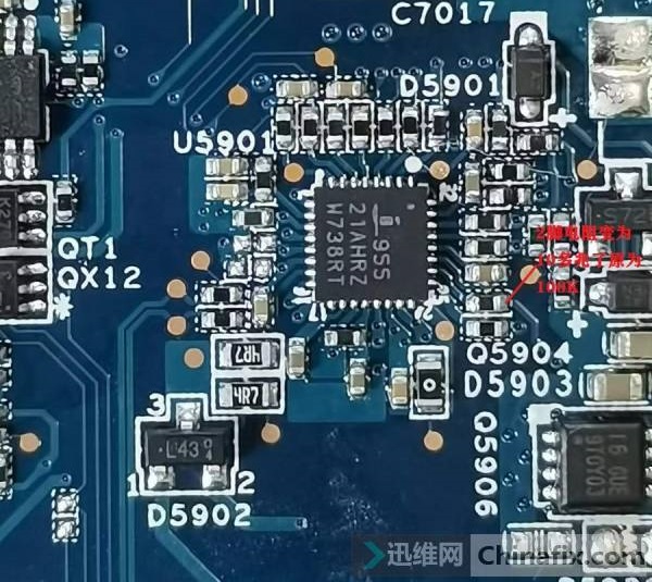
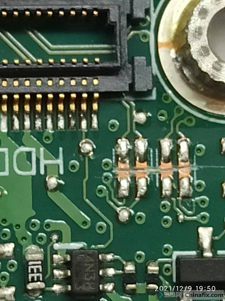
The two data lines in the middle of USB interface are checked for ground value, path and cable, and there is no abnormality. A total of two pairs of data lines of two USB interfaces are directly connected to the CPU+ bridge 2-in-1 chip, and it is judged that the external part of the CPU is damaged. This is the onboard 4-generation I3-in-1 U bridge, which can be borrowed from the redundant USB channel of CPU and flying line.
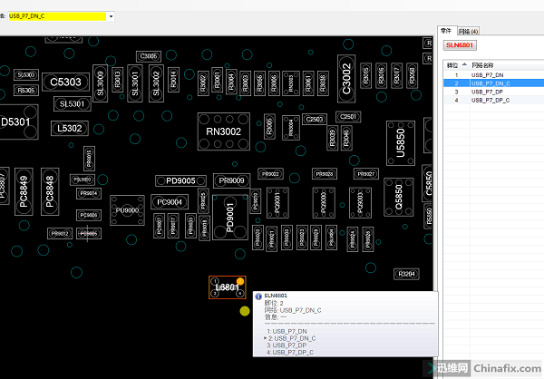
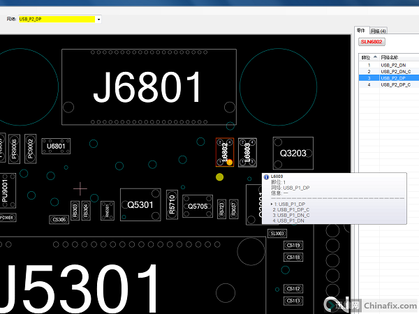
It is found that there are 7 groups of USB channels, USB_P1 and USB_P2 are two groups of failed USB data channels on the small board, USB_P3 is empty, USB_P4 is used for the camera at the top of the screen, and USB_P5 is connected to the USB3.0 interface. This has been normally skipped, USB_P6 is reserved for the touch screen, and the 0-ohm exclusion in the circuit is not installed. This channel can be borrowed first, and USB_P7 is the SD card connected to the small board.
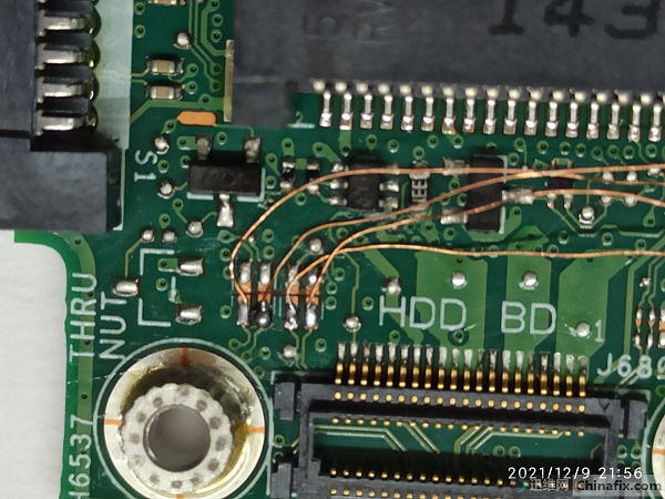
Start flying.
The first step: cut off the channels of the failed USB_P1 and USB_P2 data lines and the CPU;
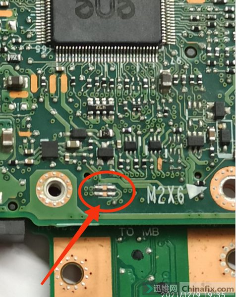
Step 2: Fly the USB_P6 and USB_P7 data lines to the corresponding positions near the interface end of USB_P1 and USB_P2, respectively;
Step 3: Make sure there is no error in commissioning.
After the test machine, it was found that the USB_P7 for SD was also broken, and it was found that the USB_P4 for the camera was less used and could be borrowed.
There are also three steps here:
The first step is to remove the connecting line between USB_P7 and USB_P2,
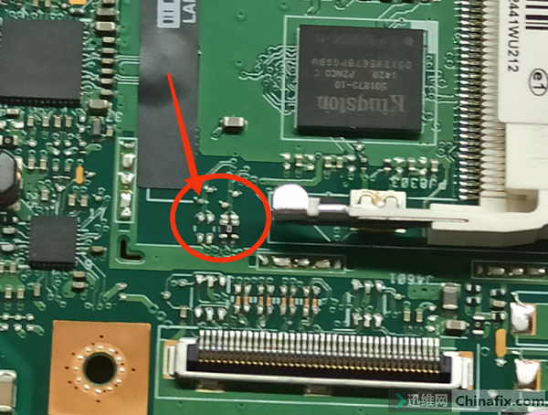
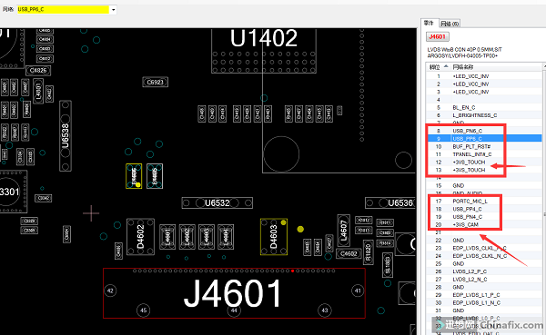
Secondly, remove the exclusion RN4605 from USB_P4 to the screen line,
Step 3: Fly the data line near the U end of USB_P4 to the corresponding position near the interface end of USB_P2.
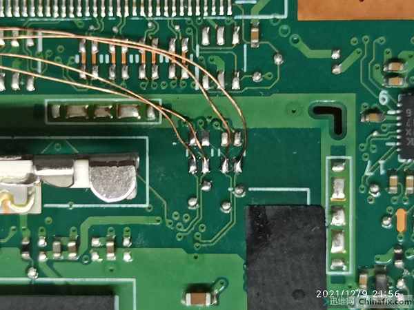
After flying, USB_P1 on the small board is connected to USB_P6;; USB_P2 to USB_P4. The test can identify the use of USB devices. Just give up the function of the camera, but don’t have to change the CPU at a high price.