Address
304 North Cardinal
St. Dorchester Center, MA 02124
Work Hours
Monday to Friday: 7AM - 7PM
Weekend: 10AM - 5PM
Address
304 North Cardinal
St. Dorchester Center, MA 02124
Work Hours
Monday to Friday: 7AM - 7PM
Weekend: 10AM - 5PM
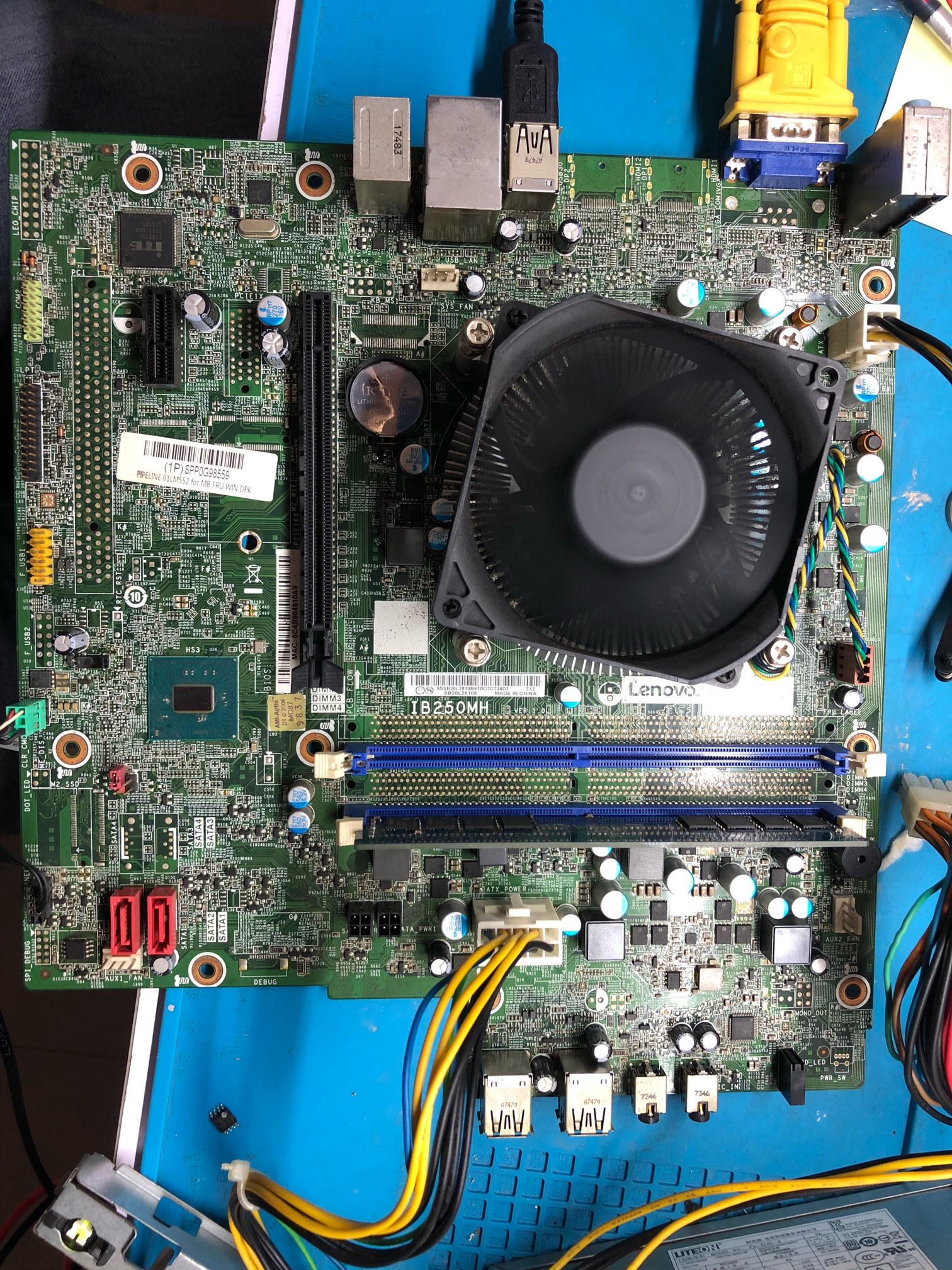
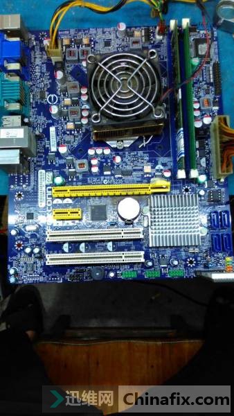
ASUS p8h61-mlx3 Plus motherboard power on and restart
Motherboard model: ASUS p8h61-mlx3 Plus r2.0
Fault phenomenon: the main board is powered on and rebooted
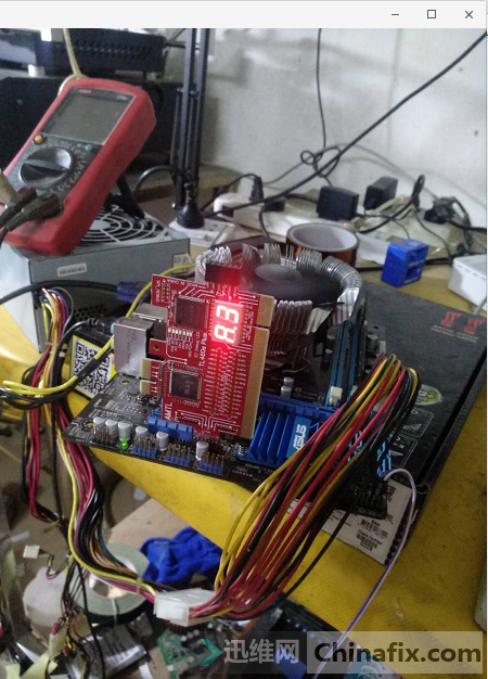
A p8h61-mlx3 Plus r2.0 motherboard. The fault is that the main board is powered on and powered off and restarted, and the diagnostic card lamp keeps flashing. It is judged that the lack of VCC is the cause.
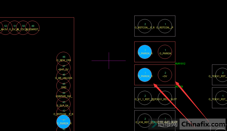
ASUS p8h61-mlx3 Plus main board power on and restart Figure 1.
Find the location map of the motherboard, look for the pwrok signal, pull down its VCC, so that the motherboard will not power off and restart again, so as to find out the missing position of VCC.
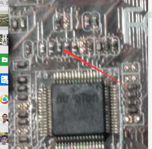
ASUS p8h61-mlx3 Plus main board power on and restart Figure 2.
ASUS p8h61-mlx3 Plus main board power on and restart Figure 3.
From the location map, it can be found that pwrok is from 3V through a resistor, and the o of Io_PWROK_R pin is connected with the upper resistance, and then pwrok signal is sent to the bridge through the above resistance. As long as the signal VCC is pulled down, the power on of the main board will not be cut off, so as to find out the lack of VCC.
Disconnect the above 3V resistance, re power on, measure each VCC, and find out the cause of the fault.
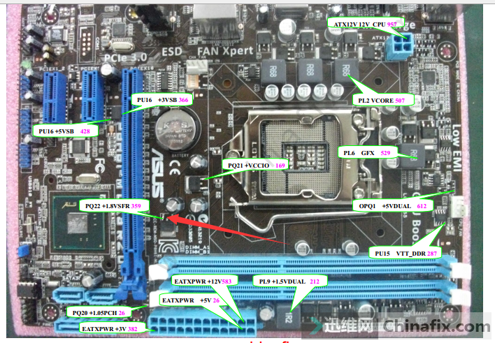
ASUS p8h61-mlx3 Plus main board power on and restart Figure 4.
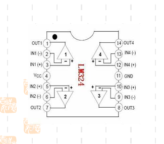
After measurement, the output of VCC is only 0.77v, which should be 1.8V normally.The field tube is controlled by an LM324.
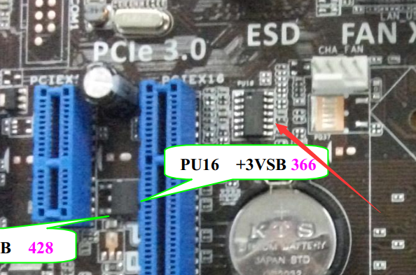
ASUS p8h61-mlx3 Plus main board power on and restart Figure 5.
ASUS p8h61-mlx3 Plus main board power on and restart Figure 6.
The fourth pin VCC 12v of LM324 is normal, and the positive input of the 10th pin is also 0.77v, which is abnormal.Negative pole is 0V, 8 pin output 2.55V, abnormal.
ASUS p8h61-mlx3 Plus main board power on and restart Figure 7.
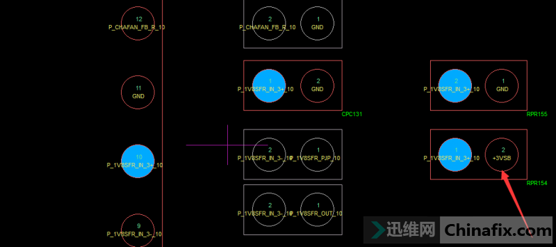
According to the location map, the 10th pin is obtained by connecting + 3vsb through two resistors in series and then connecting a small Capacitor partial voltage to obtain 1.8V positive input, while the VCC pressed out here is only 0.77v, which is obviously wrong. It is judged that the two resistances are damaged or caused by Capacitor short-circuit current.
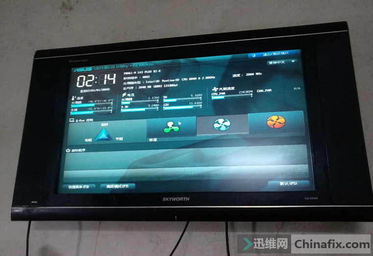
First remove Capacitor and then measure,VCC rises to 0.99v, which is still wrong. Take down the two resistances and find that one of + 3vsb’s resistances is 4.4k and the other is 10K. Decisively replace 4.4k with 8.2k resistance, weld back the resistance position of + 3vsb, weld 10K back to the original position, connect the power supply, and measure the 10th pin of LM324 has 1.82v, and VCC is normal.booting up the end of the maintenance code.
ASUS p8h61-mlx3 Plus main board power on and restart Figure 8.
ASUS p8h61-mlx3 Plus main board power on and restart Figure 9.